When designed properly, fiber-reinforced concrete (FRC) can improve long-term durability and functionality of a structure.
In this post, we walk through the ASTM C1609 test method, required testing machines and accessories, and calculating results, so you can verify the performance of your FRC.
What is Fiber-Reinforced Concrete?
FRC is concrete made primarily of hydraulic cement, aggregate and discrete short reinforcing fibers that are uniformly distributed and randomly oriented. Fiber types available include steel, glass and synthetics and lend varying properties to the concrete. Overall, FRC increases impact, abrasion and crack resistance, and improves residual strength.
But because the performance of FRC is dependent on the type, size, shape and amount of fiber used, it requires precise testing to verify the correct design for a given application.
Getting Started With ASTM C1609
ASTM International, formally known as American Society for Testing and Materials, is a globally recognized leader in the development and delivery of testing standards.
ASTM C1609 describes the test method to determine the flexural performance of FRC. The method uses FRC beams with third-point loading.
The purpose of this standard is two-fold:
- To determine the peak strength of the concrete
- To find the residual strength from the fibers after the first crack appears
The standard specifies that the test must be performed in control at very slow deflection rates—as in, the degree to which the beam is displaced under a load—with feedback from the average of two deflection sensors placed on either side of the specimen. The initial crack of the concrete can cause a jump in deflection, making control very challenging.
Because of this, a testing machine equipped with the hardware and software capable of controlling the test and recording and analyzing the data is required.
Here’s what you’ll need.
Recommended Equipment for Fiber-Reinforced Concrete Beam Testing
Three pieces of equipment are needed to perform ASTM C1609:
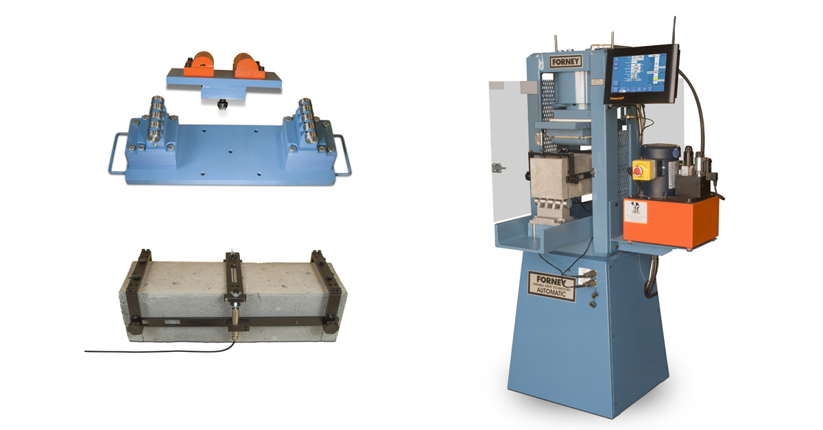
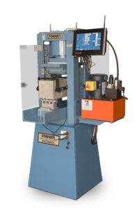
- Automatic testing machine/system
- Third-point flex accessory
- Beam transducer jig
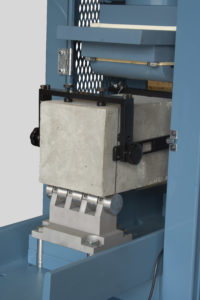
Forney supplies a modified F-325-VFD designed to perform ASTM C1609 on FRC beams. The 325 Series are versatile machines with frames manufactured from solid steel into a one-piece, welded unit that exceeds ACI recommendations. With automatic control systems, the machine brings consistency and accuracy to the testing process, ideal for the precise control that ASTM C1609 requires.
Next, you will need the third-point flex accessory (Forney TA-0166-12). This uses integrated roller supports under the ends of the beam that are free to rotate on their axes in two planes, as defined in ASTM C1812.
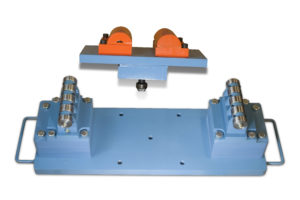
The roller design of ASTM C1812 is intended to provide a consistent and relatively low value of effective coefficient of friction at the beam supports. The bearing design incorporates metal-on-metal sliding surfaces lubricated with grease. In addition, the design allows movement in a perpendicular degree of freedom to accommodate warping that may occur during specimen fabrication.
Lastly is the beam transducer jig (Forney TA-0166-21).
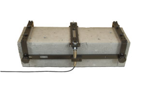
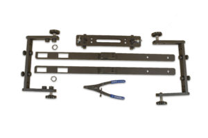
Devices such as electronic transducers must be located in a manner that ensures accurate determination of the net deflection at the mid-span, exclusive of the effects of seating or twisting of the specimen on its supports.
One acceptable arrangement employs a rectangular jig, which surrounds the specimen and is clamped to it directly over the supports at mid-depth. Two electronic displacement transducers mounted on the jig at mid-span, one on each side, measure deflection through contact with appropriate brackets attached to the specimen. The average of the measurements represents the net deflection.
ASTM C1609 Test Control & Procedure
As mentioned, test speed must be precisely controlled for the duration of the test in accordance with the deflection rates of the specimen. In addition, the prescribed rate of deflection and the total required deflection of an ASTM C1609 test combine to produce tests of long duration—30 minutes or more.
Because of this, conventional manual machines are not suitable. Manual hydraulic compression testing machines cannot adapt flow control schemes to this test regimen and will overheat.
Forney’s VFD control software adjusts control parameters throughout the test to ensure the test runs with no problems under all conditions.
Test Control
ASTM C1609 requires that the machine testing a 6” x 6” x 20” beam increase the net deflection at a constant rate between 0.0015 and 0.004 in/min.
If the beam is considered to be unstable, a lower rate (half of this range) can be used.
After a deflection of L/900, where L is the span length of the beam, the rate of deflection can be increased by as much as 0.002 in/min every 30 seconds without exceeding eight times the initial rate.
With these control parameters in mind, here’s how to run the test.
Test Procedure
- Prepare the specimen carefully and orient it according to the requirements of ASTM C1609.
- Mount the jig with the deflectometers on the beam. Ensure that each transducer makes contact with its strike plate and that there is enough travel for them to record the total deflection of 0.12 inches.
- Load the specimen on the journal bearing supports.
- Properly tare the machine.
- Run the test at the specified rates.
- Measure the beam width and depth at the point of failure.
- Record and report the information required in the C1609 test method.
Calculating Results
The results of this test method may be used for a variety of purposes, including:
- Comparing the performance of various fiber-reinforced concrete mixtures
- Monitoring concrete quality
- Verifying compliance with construction specifications
- Obtaining flexural and residual strength data on fiber-reinforced concrete members subject to pure bending
- Evaluating the quality of concrete in service
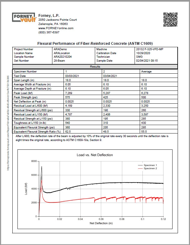
One of the challenging aspects of the C1609 test method is that it requires a calculation of the area under the load versus net deflection curve in order to determine the toughness of the beam. This value is then used to calculate the equivalent flexural strength ratio.
Calculating the area under the curve can be approximated using a spreadsheet of the deflection and load data. Each row pair of data can be used to calculate the areas of the corresponding rectangles or trapezoids. The sum of these areas is the approximate area under the curve.
Automatic Calculations
But what if you could get the results you need right away, without having to struggle through tedious calculations?
With ForneyVault, you can – because all calculations are performed automatically. When the test is complete, simply enter the width and depth measurements at the point of failure into the machine HMI, which sends all of the data to ForneyVault. Then, you can immediately generate a full report of the test, which includes all calculations required by C1609.
No copying or manipulating of data, no formulas, no time wasted – simply test and report.
The test is difficult enough, from lugging heavy beams and preparing them for testing to setting up the jig and cleaning up afterwards. Why spend additional, unnecessary time stressing about the calculations?
Conclusion
Fiber-reinforced concrete is a great option for certain applications but requires precise testing to validate its performance. Now you have a good starting place with ASTM C1609 and the equipment you need to maximize your results. Before conducting this test, please be sure to reference the current ASTM standard.
Questions about performing ASTM C1609? Need equipment or software? Contact us to discuss your needs.